To program the MSP430 on the Schmartboard, you need to be able to flash the chip and need hardware to do that. There are pieces of hardware (such as MSP-FET) which are expensive and are more suited for industrial/business applications. These tools can use 4-wire JTAG to flash the chip. However, you can flash the MSP430 from the Launchpad itself by using Spy-By-Wire (SBW) which TI sometimes calls 2-wire JTAG. 4-wire JTAG is faster than 2-wire JTAG, but obviously requires more pins on the chip (a disadvantage) and unless you are flashing hundreds of chips, the additional time SBW takes isn’t palpable.

SBW requires the following two signals in addition to making sure the target chip is powered:

  • Pin 28– TEST/SBWCLK
  • Pin 29– ~RST/NMI/SBWTDIO

The MSP-EXP430FR6989 Launchpad has an eZ-FET emulator on the top portion of the Launchpad.

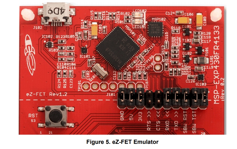
Figure 1 – eZ-FET (Picture from slau627a)

The Launchpad ships with jumpers that connect the on-board eZ-FET to the on-board chip. By removing the jumpers from GND, 3V3, SBWTDIO and SBWCLK and connecting these wires to the MSP430 pins on the Schmartboard, you can flash the chip. The Launchpad user’s guide (slau627a) describes further how to use eZ-FET to program an external target. However, the MSP Debugger’s Guide (slau647) has more in-depth details about using SBW from the eZ-FET. Some important things to note:

  • pg. 7 — The target chip must be powered from the eZ-FET emulator. Of course, you can connect the target to an external power supply once you have finished programming it. But when you are programming through SBW, make sure you use the power supply from the Launchpad.
  • pg. 40 – The LED signals on the eZ-FET can indicate problems. When both LEDs are off, the eZ-FET has become disconnected from your computer (could happen if a firmware update was unsuccessful). When only the red LED is on, the target board’s power connections are probably wrong.
  • On the MSP-EXP430FR6989 Launchpad, the wires to the target must be connected from the eZ-FET side, not the on-board chip side. This may seem obvious, but it is easy to accidentally connect to the wrong side.
  • When looking up error codes online in the TI forums, some people reference putting capacitors and pullup resistors on the SBWTDIO and/or SBWCLK lines. However, those posts usually are using 2-wire JTAG on a tool like MSP-FET. If you look at the hardware section of the Launchpad User’s guide (pg. 32), you can see the eZ-FET circuitry has the necessary pullups and capacitors built in already. Adding additional capacitors and pullups can cause problems.
  • There are no settings you need to change in Code Composer Studio to program an external chip versus the Launchpad’s on-board chip. Since the on-board chip is programmed with SBW anyways, and you are simply removing the jumpers to the on-board chip and connecting the pins to an external chip, there are no target configuration settings you have to change if you are programming an MSP430FR6989.

There are a few errors I encountered while using SBW, but I did learn from the errors and figured out why they occurred. Some of them include:

  • Unknown device. — Your chip may not be powered properly. Also, your SBW connections may be wrong. (Make sure you don’t reverse SBWTDIO and SBWCLK, and make sure you connect those signals from the eZ-FET side). Bad soldering on the SBW pins could also cause this problem.
  • Could not set target VCC. — Your chip may not be powered properly. If you were messing with settings in Target Configurations in Code Composer Studio, it is also possible you accidentally changed the target VCC to something other than 3300 mV (the recommended VCC for this chip).
  • Trouble Writing Memory Block at…. — Your chip is probably not powered properly (make sure you use decoupling capacitors!). Double check your connections and make sure your jumper wires are good (if you are using them).

As you can see, the majority of errors with SBW occur because the device isn’t being powered correctly! Make sure you follow TI’s recommendations for powering the device. That includes proper decoupling capacitors between the AVCC/AVSS and DVCC/DVSS pins. I noticed that before I added the decoupling capacitors between those pins, I would get the Trouble Writing Memory Block at…. error more often, but operation was still pretty reliable.

If you want to try an alternative to Code Composer Studio to see if your target board can be recognized, TI Tools has UniFlash which should be able to identify your chip (assuming it is powered correctly).

Prototype Video Link:

For the prototype, we created a simple Unity Game on Android. The game created involved rendering a 360 video within Unity and presenting the user with a question and a set of options to pick from.

In this video, we created a simple scenario, asking a player to buy a 2 liter bottle of Sprite. The game provides 3 options. The player use the controller to click on the available options.

  1. Go To Produce Section
  2. Go to Soda Aisle
  3. Go to Starbucks

If the player chooses either “Go toProduce Section” or ” Go to Starbucks”,  the player will be sent to that area. However, these are not the best option to get the bottle of Sprite. The message will appear on the screen “This is not the soda aisle”. After 10-15 seconds, the game automatically returns back to the main menu for the player to pick a better choice.

When the player chooses the option “Go to Soda Aisle”, the game switches to another scene with another challenge. Now, the new scene is at the soda aisle, but it tells the user “they seem to be out of 2 liter Sprite”. The game once again provides the player with different options.

  1. Talk to 2 people ( on the left)
  2. Talk to the lady holding the shopping basket (on the right)
  3. Talk to a gentlemen, who is fixing the merchandise  (on the right)
  4. Leave the soda aisle

If “Leave the Soda Aisle” is chosen, which is not one of the best answer, the message will appear on the screen “Why would you want to leave? Then you have nothing to drink”.

Then the menu scene appears again, asking the player to choose another answer. The options available are the same as the first, but giving the player another chance to make a better choice.

  1. Talk to 2 people ( on the left)
  2. Talk to the lady holding the shopping basket (on the right)
  3. Talk to a gentlemen, who is fixing the merchandise  (on the right)
  4. Leave the soda aisle

The player  can hold the controller over anyone on the game and text appears saying “Talk to this person”. Using  the Controller Pointer Click once again, they choose who to talk to.

The following choices give the corresponding responses:

a. Talk to 2 people on the left side : the message appears to explain this is not the best answer “Hmmm this person seems to be too busy”.

b. Talk to the lady holding the shopping basket: A question got prompted ” What would you like to ask them?”. There are 2 answers

i.   “I need help” : Not a very polite way to ask

ii.   “I notice you are out of sprite. Do you have anything in the back of the store” : Better choice, but not the right option because this person does not work at the store so they cannot go to the back. . The lady will reply to this choice with: “I am not the right person to ask.”

c. Talk to a gentlemen, who is fixing the merchandise: same situation as above, a question got prompted “What would you like to ask them?”. There are 3 choices:

i.   “I need help”: Not a very polite way to ask.

ii.  “I need this item”: Better choice.

iii.  “I notice you are out of sprite. Do you have anything in the back of the store”: Best choice.

Lastly, there is message “Thank you” at the end of the game. The player has to choose this to end the game.


The MPU6050 6DOF gyroscope and accelerometer is used to monitor student motion. We want to measure the student’s angular position as a function of time to measure their engagement.

A gyroscope measures angular velocity (not position). In order to measure angular position, it is necessary to integrate the angular velocity by summing up the difference in angular velocity and multiplying by the sampling period:

ThetaFinal =ThetaInitial + (Theta’*dt)

The registers are mapped as shown below:

The each value of acceleration or angular velocity is a 2-byte value, with the lower numbered register as the high byte and the higher numbered register as the low byte. To put the high and low bytes together, bit shifting is used as shown below. It is important to note that, according to the register map, these quantities are signed quantities, so we used an int to store the result of the bit shifting instead of an uint.

result[0] = ((highByte[0] << 8) + (lowByte[0]));

The code above gives the raw value of the acceleration or angular velocity. However, the raw value needs to be divided by the sensitivity factor in order to get the value of angular velocity in °/s. In the ±250 °/s range, the sensitivity factor is 131.

First, the gyroscope data was taken when the gyroscope was completely still and laid flat on a breadboard. This is to detect sensor bias, or the small amount of movement measured even though the MPU6050 is not moving at all. The results are shown below:

The average value of sensor bias for the x, y and z measurements of angular velocity were

Axis Angular Velocity (degrees/s)
X -0.311
Y -2.28
Z 0.42


Raw data was collected and sent to a computer terminal by using the Bluetooth module. (This data can also be sent to a terminal in Unity through the same process. However, data was exported directly to a computer in this case to make importing to MATLAB easier for prototyping purposes).

The raw data was processed in MATLAB by dividing by the appropriate sensitivity factor. The graphs of angular velocity are shown below. The data is rather noisy and would benefit from filtering. However, angular positions were calculated from integrating these angular velocity values through MATLAB’s cumtrapz function, which allows integration of discrete data.

To create the following figures, the MPU6050 was laid flat on a breadboard, and the breadboard was placed on the arm of a swivel chair. The chair rotated from approximately 180 degrees. The gyroscope output is graphed below, and the processed gyroscope data (to convert to angular position) is also graphed. The accelerometer data was used to calculate the angle as described in the Background/Phenomenology section. There was very little rotation in the x and y planes, as the chair itself was only rotated about the z axis. The output in the x and y planes is noisy, and we may be able to get a less noisy signal if we look in to more complex calibration techniques.

As shown below, there was very little change in x angular position and y angular position, as expected, since the chip remained flat on the breadboard.

As shown below, the gyroscope data indicates that the chair moved approximately 180 degrees, as expected. Since the measurement of chair rotation is yaw, (the axis is parallel to the direction of gravity) the accelerometer cannot sense this movement, which is why the accelerometer data is not in line with the gyroscope data.

Beside the player’s selection choice, we also want to provide the player’s reaction time to the instructor.

My task was to display a timer during the game (in second). Every time  choose a selection, then the timer will restart at 0 and counting up.

I was able to display a message Time: and the amount of time increasing within second. 

I was not success on restart the new timer after player select an answer. It seems like it does restart to 0, but two timers is running on top of each other. I am still working on it and will update on the process.

At the end of the game, a file contains for of the player’s selections will be provide to the professor.

There are server ways to create a file in C# within Unity, I used  the StreamWriter and FileInfo to be the components for this task.

I created a C# with public class name: Tracking. Within the class, I created a function called ToFile with parameter accepting a string.

I created a file call: myfile.txt and save it under a Asset/TextFile directory.

Using Event Trigger with event type: Pointer Click. Overtime player choose click on the button, it will save that into a file. Something like this:


The literature and patent review have been posted as new pages on this page. In case you do not see them, on the search bar please type patent review or else and it will take you to the page. If you have any further questions, please contact us.

In order to create the best possible scenario for the Mason LIFE program, we decided to have the setting be at the grocery store Giant, on Braddock rd. This one was specifically chosen because it is commonly frequented by the students of the Mason LIFE program, and thus would provide a sense of familiarity as well as a way to learn for future visits. Before conducting the filming, I was in contact with the store manager and explained to him why we would like to be able to film there and asked what the best time would be. He excitedly allowed us to conduct the filming at the store because he was really interested in the purpose of our project, and told us we could come in and do it any day but that we should probably do it right at opening so there are as few other customers there as possible.

On the day of the filming, myself, Marcela Angulo, and Coralia Aguilar went to conduct the process. Myself and Marcela each brought one person to act in the scenario and Coralia brought two. We assigned on person to play the “not-busy customer”, one person to play the “employee” (who Giant graciously let borrow a shirt and name tag so the scenario would be more realistic), and the other two people to play the “busy customers”. We had prepared a shot list before going to do the filming so that we could do so as quickly as possible. We were able to film all of the “actors'” lines as well as some stock footage in different settings within the store to have in the background when choices are show on the screen during the game.

Overall the filming went really well. We only encountered a couple aspects that made it more difficult than we had anticipated. The first issue was that the music and ads playing over the store speakers were pretty load, so the actors had to make sure that they said their lines pretty loudly. Also, the tripod we were using was not tall enough to be at an average eyesight height, so we had to put it on top of boxes in order to make the footage more realistic. Finally, one thing that we will be sure to pay closer attention to next time we film is to make sure that the footage that will be used as a loop is able to loop more naturally and does not cut back to the beginning of the shot in a choppy and unnatural way.

This experience was really helpful to know how to improve for the next time we have to film more scenes for the game, or if we end up re-filming the scenes we filmed that day.

We met with Mr. Mclean briefly to schedule an appointment with him where we could get tutorials on how to record and edit the footage we recorded. We were able to receive the 360 camera  to start recording some sample footage to see how to work with it. To get some more insight we schedule an appointment for the following Friday, Nov. 2.

In our follow-up meeting with Mr. McLean about 360-degree video, we were able to go into more detail about the exact steps needed in order to correctly use the footage. First, he showed us briefly how to make sure the settings on the camera itself were setup correctly for the type of video footage we will be taking. We then saw a brief example on how to take the footage through the app that corresponds to the camera so that the footage can be taken while you stand in a different room so you will not be in any angle of the shot. Then we downloaded the correct software so that we could use the footage from the camera. The next step that Mr. McLean showed us was how to upload the footage correctly through the software downloaded so that it stays in 360-degree formatting. Then we had to use other software in order to stitch the footage into the 360-degree footage that is understandable to the human eye. Finally, Mr. McClean gave us a couple of tutorials to do on our own so we can understand the advanced editing that we may need if we go further than simply just using the clips we take from the camera. Mr. Mclean also noted that if we have any other questions as we go on with the project, we can schedule another meeting with him to help us, as well as use resources from any of the software or websites he provided to us.

Final Literature Review

This is our final literature review draft. In this we discuss research that we have done on how virtual reality can work with education and with those with intellectual or developmental disabilities (IDD) and those specifically with autism. There were a couple studies based on research about how virtual reality headsets can improve education in all facets. However, there was no exact experimental research done with virtual reality headsets, specifically, to test education for students with IDD. The research in the literature referenced in this literature review looks at many different derivations of virtual reality used within education, and all of the research and testing has shown that it has only had a positive outcome when the right equipment is used. Each piece of literature is discussed at length with greater detail in the attached document.

« Previous PageNext Page »