November 28, 2018
The MPU6050 6DOF gyroscope and accelerometer is used to monitor student motion. We want to measure the student’s angular position as a function of time to measure their engagement.
A gyroscope measures angular velocity (not position). In order to measure angular position, it is necessary to integrate the angular velocity by summing up the difference in angular velocity and multiplying by the sampling period:
ThetaFinal =ThetaInitial + (Theta’*dt)
The registers are mapped as shown below:
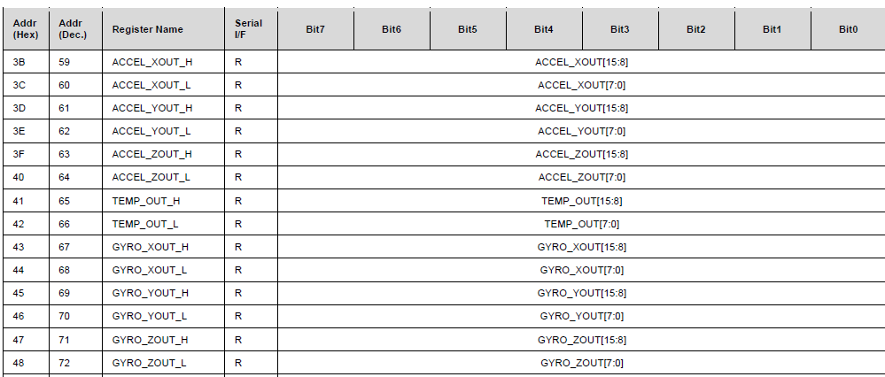
The each value of acceleration or angular velocity is a 2-byte value, with the lower numbered register as the high byte and the higher numbered register as the low byte. To put the high and low bytes together, bit shifting is used as shown below. It is important to note that, according to the register map, these quantities are signed quantities, so we used an int to store the result of the bit shifting instead of an uint.
result[0] = ((highByte[0] << 8) + (lowByte[0]));
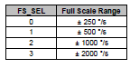
The code above gives the raw value of the acceleration or angular velocity. However, the raw value needs to be divided by the sensitivity factor in order to get the value of angular velocity in °/s. In the ±250 °/s range, the sensitivity factor is 131.
First, the gyroscope data was taken when the gyroscope was completely still and laid flat on a breadboard. This is to detect sensor bias, or the small amount of movement measured even though the MPU6050 is not moving at all. The results are shown below:
The average value of sensor bias for the x, y and z measurements of angular velocity were
| Axis | Angular Velocity (degrees/s) |
| X | -0.311 |
| Y | -2.28 |
| Z | 0.42 |
Raw data was collected and sent to a computer terminal by using the Bluetooth module. (This data can also be sent to a terminal in Unity through the same process. However, data was exported directly to a computer in this case to make importing to MATLAB easier for prototyping purposes).
The raw data was processed in MATLAB by dividing by the appropriate sensitivity factor. The graphs of angular velocity are shown below. The data is rather noisy and would benefit from filtering. However, angular positions were calculated from integrating these angular velocity values through MATLAB’s cumtrapz function, which allows integration of discrete data.
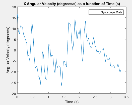
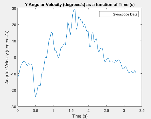
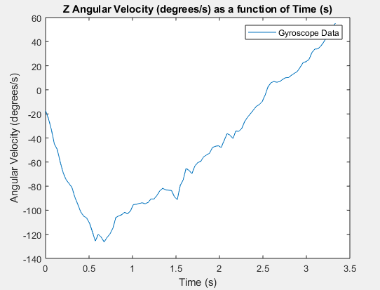
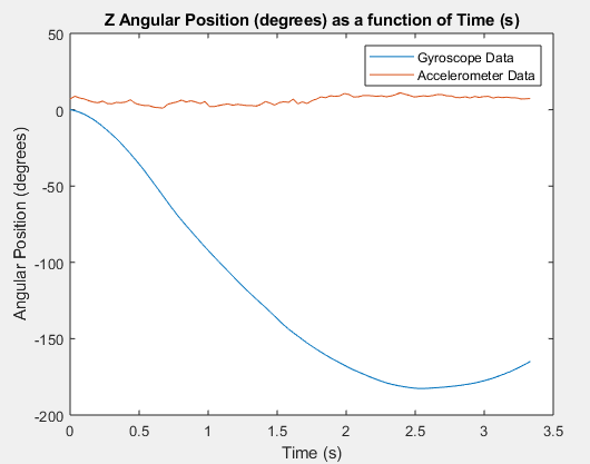
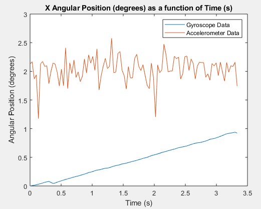
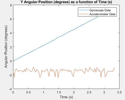
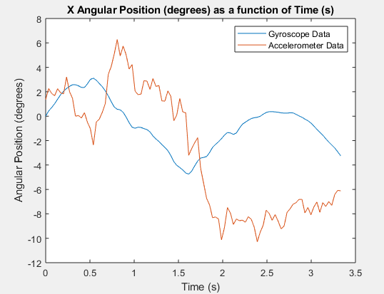
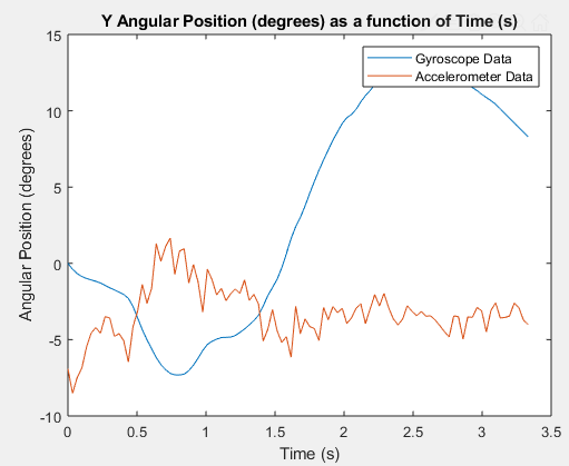
To create the following figures, the MPU6050 was laid flat on a breadboard, and the breadboard was placed on the arm of a swivel chair. The chair rotated from approximately 180 degrees. The gyroscope output is graphed below, and the processed gyroscope data (to convert to angular position) is also graphed. The accelerometer data was used to calculate the angle as described in the Background/Phenomenology section. There was very little rotation in the x and y planes, as the chair itself was only rotated about the z axis. The output in the x and y planes is noisy, and we may be able to get a less noisy signal if we look in to more complex calibration techniques.
As shown below, there was very little change in x angular position and y angular position, as expected, since the chip remained flat on the breadboard.
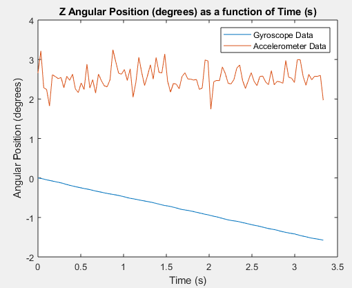
As shown below, the gyroscope data indicates that the chair moved approximately 180 degrees, as expected. Since the measurement of chair rotation is yaw, (the axis is parallel to the direction of gravity) the accelerometer cannot sense this movement, which is why the accelerometer data is not in line with the gyroscope data.