January 23, 2019
It is important to follow TI’s recommendations when powering the chip, which are outlined in the Recommended Operating Conditions in SLAS789D, pg. 29. The Recommended Operating Conditions also clearly states that all VCC pins and all VSS pins should have the appropriate voltages applied to them, even if you aren’t using the chip’s analog capabilities.
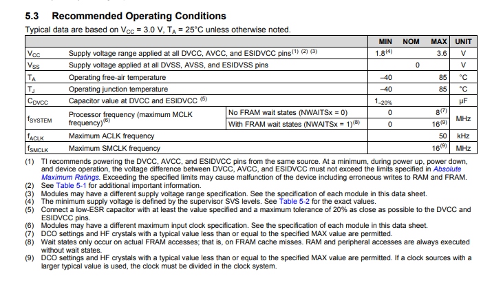
Taken from SLAS789D
On the 100 pin IPZ package, there are a total of five VCC pins (which should be connected to +3.3 V):
- Pin 99 – DVCC3
- Pin 79 – AVCC1
- Pin 75 – ESIDVCC
- Pin 58 – DVCC2
- Pin 27 – DVCC1
There are a total of seven VSS pins (which should be connected to GND/0.0V):
- Pin 98 – DVSS3
- Pin 86 – AVSS2
- Pin 83 – AVSS1
- Pin 80 – AVSS3
- Pin 76 – ESIDVSS
- Pin 57 – DVSS2
- Pin 26 – DVSS1
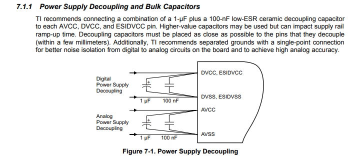
The Recommended Operating Conditions also show the placement of decoupling capacitors between each set of VCC and VSS pins:
When all of these connections are made properly, and SBW connections are made properly, the chip should be easy to flash in Code Composer Studio. Use a multimeter to check that each pin is receiving the appropriate voltage.